What if we want to graph the pressure changes in air made by somebody playing the flute? The graph might look a bit like this:
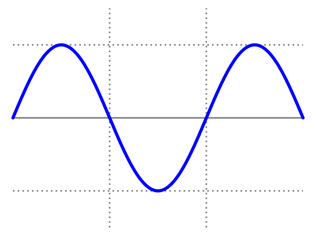
The vertical axis is pressure and the horizontal axis is time. We can see the pressure increase, decease and increase again. The idealised wave form shown here is a sine wave. This wave has exactly one frequency in it and is the simplest possible wave form.
If you generate a sine wave in your DAW and then zoom way in, you’ll see exactly the same shape, but in that case, the Y axis is how much the speaker cone will offset when we play back the sound. This makes sense. The speaker needs to push the air to make the sound wave. If we were looking at an analogue signal to the speaker via an oscilloscope, the Y axis would be the amount of voltage.
If the wave is taller, the speaker moves more air and the sound is louder. The height of the wave is the amplitude.
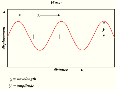
The distance from one peak to another, λ, is the wavelength. If the wavelength is shorter, the speaker cone moves faster. A faster movement and a shorter wavelength means a higher frequency.
We’ve measured from the peaks, but we could measure from any point along the curve, for instance, from the zero crossings, as long as the wave has been through a complete cycle.
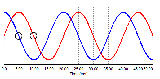
If waves start at different points but have the same wavelength, we say they are the same frequency but have different phases. In figure 3, the red line starts at zero and is a sine wave. The blue line starts at 1 and is a cosine wave. They both are the same frequency.
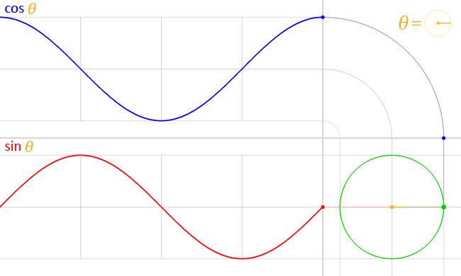
In figure 4, we can see an animation of the cosine and sine wave moving at the same frequency and how they are related to each other.
Summary
In the last three posts, we learned that sound is made up of tiny pressure waves which travel at 340 m/s. When these strike our ear drums, this in turn causes our basilar membrane to vibrate. Distinct vibrations on the membrane are heard as distinct frequencies.
We can graph the pressure waves of the sound. This is the same as the waveform graph in our DAW and is the same as the change in voltage of the signal going to our speakers. All signals going to our speakers have an amplitude, where taller is louder. Periodic sounds, like sine waves, also have a frequency, where a shorter wave length is a faster vibration and a higher pitch.
Waves can have the same frequency but be out of phase with each other, so their peaks and troughs do not line up.
Supplementary Reading
Everest, F.A. and Pohlmann, K.C. (2015). Master Handbook of Acoustics. Sixth edition. New York: McGraw-Hill Education. – Chapter 1
Activity
Materials
- Audacity
- Sonic Visualiser
- A Microphone
- An audio interface (or other way to get microphone input into your computer.)
- A quiet corridor with a wall some meters distant
- A tape measure
- Optional: a room thermometer
Method
Place your microphone so it points at the wall. Start recording into Audacity. Stand behind the microphone. Clap. Stop recording.
Check your recording. You should have two impulses on the recording. One is the loud clap and the second is the echo of the clap. If these are too close together, move further from the wall.
Once you have a clean recording, export it as a WAV file and open it in Sonic Visualiser. Use the tape measure to measure how far you are from the wall.
Listen for when the first echo appears, and see if you can measure the distance in milliseconds using the display.
You might need to experiment a bit with the zoom controls, and possible other controls in Sonic Visualiser to make it clearer to see where the echo appears.
Also, it won’t necessarily be an exact point, so you may have to use your judgement.
Remember that the sound has to travel to the wall and back, so the total distance is double what you measured.
What was the speed of the sound. Is it what you expected? If you were able to measure the temperature, how much impact did that have on the speed?