(Scroll to the bottom for the video)
My friend Evan suggested that I could just remove all the organ electronics and replace the MIDI jack and this would likely work without posing a danger to my laptop. So I finally did.
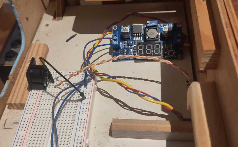
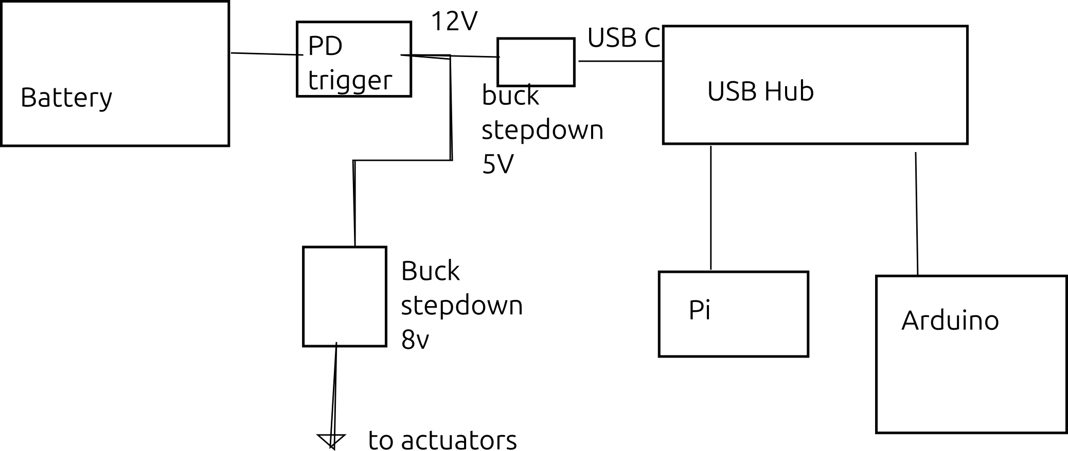
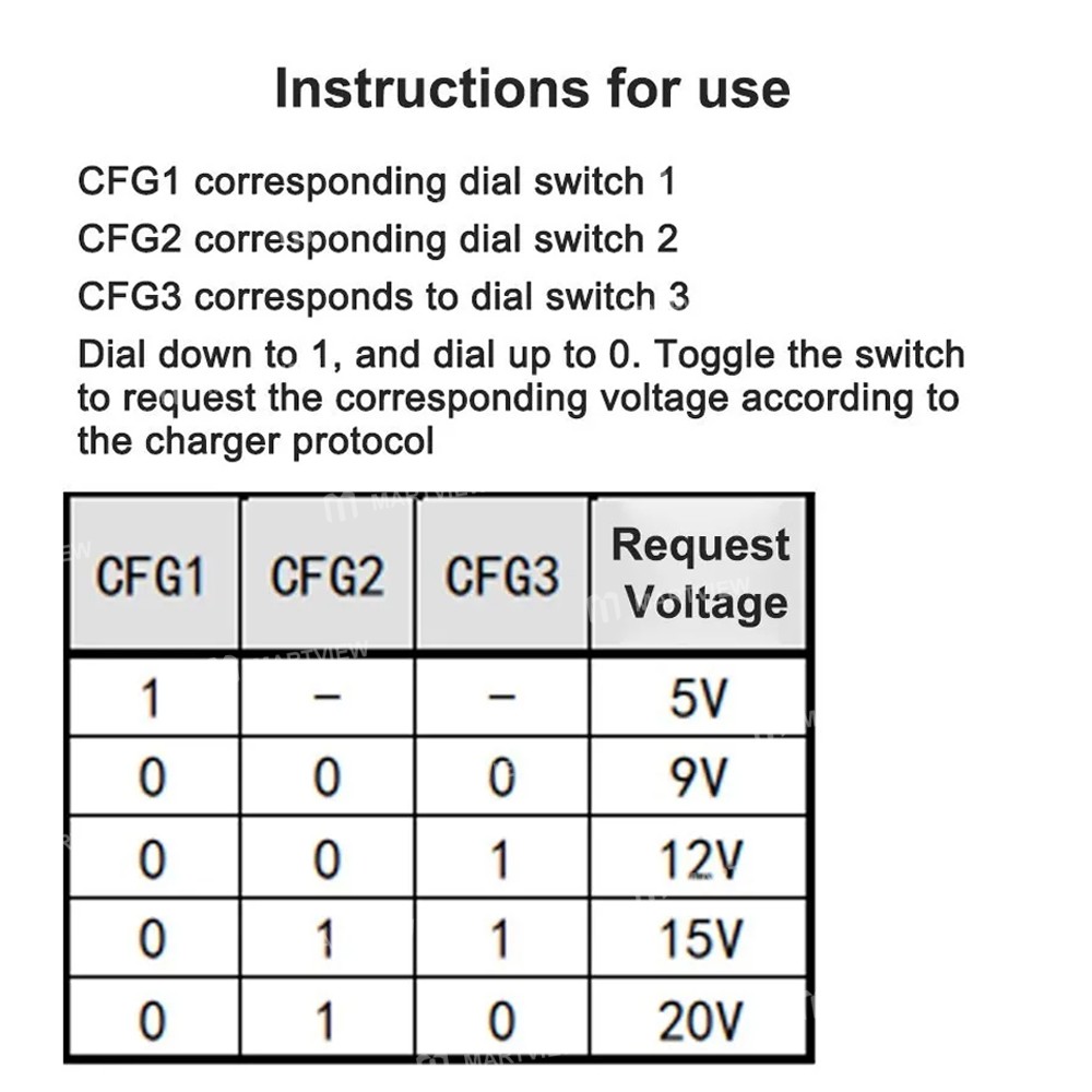
I replaced the original batteries with a phone charging battery from Argos. It goes to a PD trigger – a USB C board that tells the battery something is using it and draws a steady DC voltage. I’m drawing 12 volts.
This voltage is then split to go to two buck stepdown boards. The one currently in use is 8v, because the part of the organ in the wind chest uses 8v. The other part of the system is not yet installed, but will run on 5v.
The actuators have three power cables, a heavy yellow ground and a red and a blue wire both at 8v.
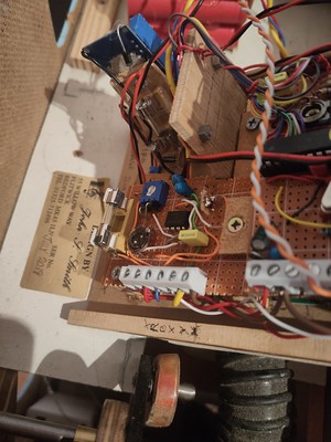
Then there are the MIDI wires.
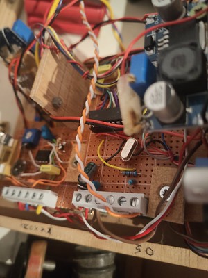
Fortunately, looking at the existing MIDI jack revealed which wire was which.
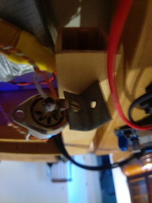
Simply compare the nail position with the MIDI spec.
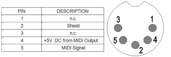
Fortunately, this followed the spec, as the data changed too fast to be discovered via voltmeter.
The voltmeter did let me know that the PD trigger I bought has on and off labelled in reverse on the device.
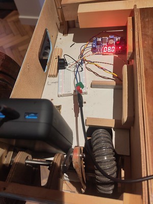
The black thing on the breadboard is the new input MIDI jack.
And it worked.
So I brought it to the algorave and live coded it with SuperCollider.